| Vehicle Physics |
This article discusses how to simulate vehicles, like cars.
This topic contains the following sections:
There are 2 common ways to implement car physics:
Constraint Car:
The ConstraintCarSample in the Samples shows how to implement a very basic constraint car, where a car is created using rigid bodies and constraints. The chassis is a box and the wheels are cylindrical bodies. The wheels are connected to the chassis using constraints (HingeJoints for the rear-wheels, Hinge2Joints for the steerable front-wheels). The wheel rotation is controlled using motor constraints.
This works in principle but has a few disadvantages: We would need more complex joints to simulate suspension. The sliding behavior of wheels is different from standard rigid bodies. Real wheels aren’t rigid bodies. We have a lot of constraints that have to be configured very carefully. Etc. - For action games a different simulation method is much simpler and more customizable:
Ray-cast Car:
In a ray-cast car the chassis is a rigid body, but the wheels are only short rays that sample the ground. In the simulation, there are no cylindrical shapes or rigid bodies for the wheels. The wheels are only rendered as part of the visual model. A ray-cast car is simpler, more efficient and gives us a lot of tuning options.
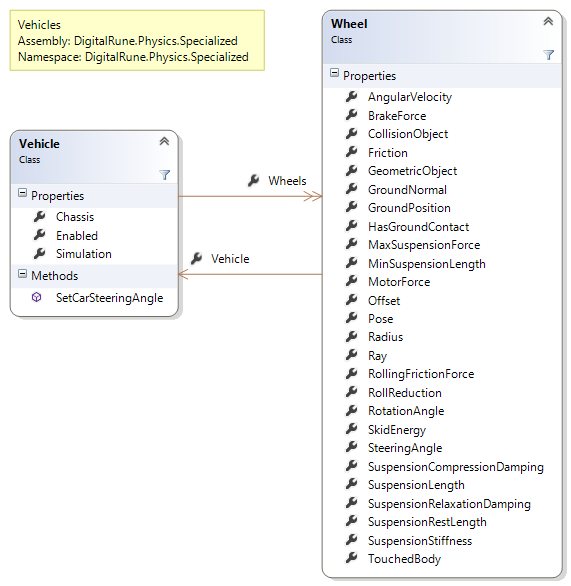
The class Vehicle implements a ray-cast car which can be used to simulate vehicles, like racing cars, with a variable number of Wheels.
The VehicleSample (see Samples) shows how to use vehicle physics.
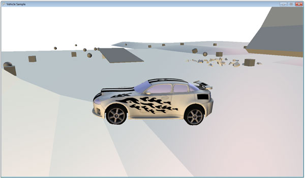
Here is a video of the vehicle sample:
This section describes the vehicle implementation of the Vehicle class and how it is used in the VehicleSample.
The chassis
We use a single rigid body for the chassis of the car. You can use a simple box or a composite shape consisting of two boxes (lower car part + upper car part) as the shape. If you use a more detailed car model, it is better to use the convex hull of the mesh vertices as the shape because triangle meshes are not optimal for collision detection.
The original car model used in the sample has about 10,000 vertices – its convex hull about 500 vertices. That’s still quite a lot of vertices. Therefore we simplified the convex hull: Our convex hull generator allows to set an upper limit for the allowed number of vertices. In our example we set an upper limit of max. 64 vertices. The simplified convex hull has less vertices than the original convex hull. However, it is also slightly bigger. That’s the disadvantage of a simplified convex hull.
The convex hull worked quite well in most cases. Except in uneven terrain the car chassis could hit a hump in the ground and stop the car. The mesh of our sports car was too close to the ground for some uneven off-road parts in our level. To give the car a bit more freedom, we shrank the convex hull shape by a small factor (using a negative skin with of –4 cm).
In the sample the chassis shape is created like this:
// 1. Extract the vertices from the car model.
TriangleMesh mesh = TriangleMesh.FromModel(_car);

// 2. (Optional) Create simplified convex hull from mesh.
DcelMesh convexHull = GeometryHelper.CreateConvexHull(
mesh.Vertices, 64, -0.04f);

// 3. Create convex polyhedron using the vertices of the
// convex hull.
ConvexPolyhedron chassisShape = new ConvexPolyhedron(
convexHull.Vertices.Select(v => v.Position));
The mass frame
The mass frame defines the center of mass of a rigid body. Normally, a physics engine computes the center of mass automatically from the given shape. For the chassis, the automatically computed center of mass (COM) is not optimal because it assumes a uniform density in the whole chassis. Therefore, we adjust the position of the COM manually. And we apply another trick: We artificially place the COM lower to the ground. It can even be outside of the shape under the ground! Lowering the COM makes the car more stable. Cars with a high COM are unstable in tight curves and tend to overturn. Here is how we create the mass frame and the final rigid body for the chassis:
// The mass properties of the car. We use a mass of 800 kg.
MassFrame mass = MassFrame.FromShapeAndMass(
chassisShape, Vector3F.One, 800, 0.1f, 1);
Pose pose = mass.Pose;
pose.Position.Y -= 0.5f; // Lower the center of mass.
pose.Position.Z = -0.5f; // Center should be below the driver.
mass.Pose = pose;

RigidBody chassis = new RigidBody(chassisShape, mass, material);
Material
For the material: We use a standard material with standard restitution and friction values. The material is only important when the car chassis slides along walls or the ground in crashes.
Wheels
We create a ray for each wheel. The ray of a wheel starts where the suspension is fixed to the chassis. It shoots down and its length is the suspension length plus the wheel radius. These rays are used to detect the ground distance and the normal vector of the ground in each frame. And in each frame we have to apply 3 forces per wheel:
- suspensions force,
- side force
- and forward force.
Suspension
The suspension is modeled as simple damped spring that has a spring constant (suspension stiffness) and a damping constant (suspension damping). Actually, we use two different damping coefficients: one when the suspension is compressing (higher) and another one when the suspension is extending (lower than the compression damping). The current suspension length is hit distance of the ray - wheel radius. We assume that the suspension spring is at rest when it is fully extended. The suspension force in pseudo code is
suspensionForce = stiffness * (restLength – currentLength) + damping * (previousLength – currentLength) / deltaTime
This force is applied to the chassis at the position where the wheel touches the ground. And an equal but opposite force is applied to the ground.
Side force
The goal of the side force is to stop any sideways motion of the wheel. We compute a vector in the ground plane that is orthogonal to the current rolling direction. Then we compute the force that is necessary to stop the sideways motion of the chassis at the wheel ground position.
The side force is computed but not applied immediately.
Forward force
The forward force is applied to the chassis at the wheel ground position. It acts in the forward direction of the wheel and lies in the ground plane. This force accelerates the car (user steps onto the gas pedal) or decelerates the car (braking).
The forward force is further divided into the motor force and the brake force. The motor force increases when the user presses the forward button. It decreases and can get negative when the user presses the backwards button. The motor force returns to 0 when the user does not press the forward or backward buttons.
The brake force is set to a constant value when the user presses the handbrake button. If the motor force is larger than the brake force, then we use the difference as the magnitude of our forward force. If the brake force is larger, then we cannot simply use the brake force value as the magnitude of the forward force. The brake force could be too large and accelerate the car into the opposite direction - especially when the car is at rest. To compute the exact brake force, we compute the force that would stop any car motion in the forward direction. Then we limit this force by the current brake force.
After that we know the magnitude of the forward force – but we do not apply this force yet.
Sliding
The computed forward and side forces are ideal, in the sense that the wheel is not sliding. But sliding a.k.a. drifting is one of the fun parts of racing games and we need to model this too.
When an object is pushed tangential to the ground, a friction force acts against the movement. This friction force is limited by
maxFrictionForce = frictionCoefficient * normalForce
For each wheel, we assume a constant friction coefficient. And we already know the normal force: It is simply the suspension force computed earlier. This maxFrictionForce limits the possible forward and side forces. We sum up the forward force (in forward direction) and the side force (in side direction) and get the sum force that lies in the ground plane. When the magnitude of this force is larger than the maxFrictionForce, the wheel is sliding and we clamp the magnitude to the maxFrictionForce. The clamped force is applied to the chassis at the wheel ground position.
We further compute the so-called skid energy, which is the energy of friction [1] when the car is sliding. This information can be used to control skid sounds or rendering of tire marks.
One important aspect of this sliding model is that forward force and side force are summed up before they are clamped. That means, the side force is indirectly limited by the current forward force. For example, if the car is at rest, it is hard to push the car sideways. But if the car is accelerating or decelerating, the maximal side force is reduced. In other words: Drive at a high speed in a curve and hit the handbrake, the braking wheels will start to slide.
Wheel rotation
Our wheels are only rays, still we have to compute a wheel rotation for visual wheel models. We simply compute the linear point velocity of the chassis at the wheel ground position in the forward direction (in the ground plane). The angular velocity of the wheel is then
wheel.AngularVelocity = forwardVelocity / wheel.Radius;
and the rotation angle is
wheel.RotationAngle += wheel.AngularVelocity * deltaTime;
You might want to change this. For example: Immediately stop the wheel rotation when the handbrake is active – for a dramatic effect.
Steering
To steer the car, we set the steering angle of the wheels. The steering angle defines the forward direction in which the forward force is applied. (The side force is always normal to the forward force.) The steering angle changes when the user presses the steering buttons (e.g. the left/right arrow keys on the keyboard). The steering angle does not change instantly. Instead, it changes over time until it reaches the maximal allowed steering angle. When the user is not pressing a steering button, the steering angle goes back to 0.
For very high speeds it is advisable to reduce the maximal allowed steering angles – small angles will suffice and keep the car controllable.
Tuning
Good car physics needs a lot of tuning and also depends on the type of game. Following parameters should be considered for tuning:
- Suspension stiffness and damping: Use a high stiffness for sports cars and a lower stiffness for off-road cars and normal cars.
- Center of mass position: Shifting the COM can significantly change the driving behavior.
- Wheel friction: Use different friction for front and rear wheels to create oversteering or understeering behavior.
- Motor forces and braking forces: Tune the maximal forces and decide where to apply the forces (front-wheel drive vs. rear-wheel drive vs. all-wheel drive).
- Roll reduction: This a parameter that we haven’t discussed so far. When it is 0, the wheel side forces are applied at the wheel ground position. When it is > 0, the side force are applied on a higher position. This makes the car more stable in curves. It reduces the sideways tilt in curves or the chance that the car will overturn. Changing this parameter can also have significant effects.
- Gravity: Maybe use a higher gravity for the car.
- Extra yaw torques (or angular impulses) can be applied to improve turning and create artificial sliding behavior.
- Use extra damping forces if the car is too unstable.
- Change the wheel friction depending on the current wheel velocity to create the perfect drifting behavior.
Possible extensions
The implemented car physics can be improved in several aspects: (The vehicle source code is available for licensees!)
- Consider gears and transmission when computing the wheel motor forces.
- Use more ray casts per wheel instead of only a single ray. Or, use a linear shape cast with the cylinder shape. (A linear cast or shape cast is similar to a ray cast, but where a ray cast shoots a single point, a shape cast shoots a larger shape and computes the first time of impact. In DigitalRune.Geometry this can be done using GetTimeOfImpact queries.)
- Use hard constraints when the suspension is at its minimum length. Currently, when the car falls with a high velocity, the wheels can sink into the ground. The suspension force is not high enough to prevent this. For this case we could add a constraint (e.g. a LinearLimit) that is active when the suspension is max compressed.
Car camera
In a third-person view the camera can be fixed behind the car. This is used in our sample but does not look very dynamic. A spring-based chase camera, like in the AppHub Chase Camera sample, could look better. Or, compute the camera direction as a linear interpolation of the current car orientation and the current driving direction.
The ConstraintVehicleSample (see Samples) contains an alternative vehicle physics implementation. The new implementation is very similar to the Vehicle class described above. It also uses rays to represent the wheels, but instead of a force effect it uses constraints which model the wheel forces.
Using constraints is more difficult than applying forces. However, they improve stability. For example, when a stiff spring is modeled with forces, the simulation will easily become unstable. Constraints can be used to model stable springs [2].
The alternative car physics implementation provides the following benefits:
- Stable springs, which means that this implementation can be used with very rigid wheel suspensions.
- No sliding on slopes. (The other car implementation slides down on slopes. To park a car on slopes you need to use some tricks.)
- Braking wheels do not rotate.* – This is a simple change, which only affects the visuals and not the actual simulation. In the previous implementation the wheels rotate as long as the car is moving. Simply stopping the wheels while user presses the brake button is a good feedback and visually more interesting.
- A broad phase filter disables collision detection for static geometry.* This avoids some unnecessary collision computations and contact data and thereby improves performance.
*The last two changes could also easily be added to the old vehicle sample.
The disadvantage of the new implementation is that it is probably more difficult to understand; hence, more difficult to adapt.
[1] "Energy of Friction", Wikipedia, http://en.wikipedia.org/wiki/Friction#Energy_of_friction
[2] Erin Catto: "Soft Constraints – Reinventing the Spring", GDC 2011, http://code.google.com/p/box2d/downloads/detail?name=GDC2011_Catto_Erin_Soft_Constraints.pdf