| Constraints, Contacts and Joints |
This section introduces the concept of constraints.
This topic contains the following sections:
A constraint is a simulation rule that limits the movement of two bodies relative to each other. In other words, a constraint restricts the degrees of movement of a body relative to another body. Here are a few examples:
Contact constraints ensure that bodies cannot move through each other. The constraints also make sure that the velocity of colliding bodies is partially reflected to create a bouncing behavior. They also create friction if bodies slide on each other.
A ball-and-socket joint is a constraint that connects to bodies, like a joint of the human body that connects two limbs.
A hinge joint can connect a door to a wall to create a swinging door.
A revolute joint can connect a wheel to a car.
An angular velocity motor can control a wheel so that it rotates with a given constant angular velocity.
The namespace DigitalRune.Physics.Constraints (see also Class Diagram of Namespace DigitalRune.Physics.Constraints) contains several constraint types that can be added to the Constraints collection of a Simulation. The simulation will check all constraints in each simulation time step and will apply forces to the rigid bodies, so that the constraints are satisfied. If a constraint is violated (e.g. a rigid body penetrates another rigid body therefore violating a contact constraint), the simulation will add velocities or apply position corrections, so that the constraint error is removed in the next few simulation steps.
All constraints are two-body constraints - they connect exactly two bodies. However, it is often necessary to constrain a single body relative to world space. For example, it might be necessary to fix a body in the sky, or to hold a body at the current mouse cursor position. In these cases the special rigid body SimulationWorld can be used. World is an abstract rigid body that can be set as the second body in a constraint.
A ball-and-socket joint connects one point of body i with one point of body j. The body points that are connected are called the constraint anchor points or, short, constraint anchors.
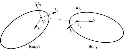
Constraint anchors are also called attachment points. Each constraint anchor is fixed on the rigid body. And in general, the anchor points are not in the origin of the rigid body nor in the center of mass. A constraint anchor does not only define a position, it defines a coordinate system with three constraint axes. The constraint axes are required for constraints that restrict movement. For example a hinge constraint will make sure that the constraint anchor points are touching and that one constraint axis - the hinge axis - is always aligned. More complex constraints allow to restrict translations or rotations around multiple constraint axes.
Many constraint classes have properties that allow to define the constraint anchor using the type Pose. The pose defines the position of the anchor point and the orientation of the constraint axes relative to the local space of the rigid body.
Specifying the correct orientation for the constraint anchor pose is not always easy. It is helpful to remember: The orientation of the constraint anchor pose is 3 x 3 rotation matrix, and the columns of this matrix are identical to the constraint axis vectors in local space of the body! The first column of the orientation matrix is the normalized direction of the constraint x axis. The second column is the normalized direction of the constraint y axis. The third column is the normalized direction of the constraint z axis. (All relative to the local space of the body.) |
It is allowed to define an anchor point that lies outside the shape of the rigid body. |
A few practical examples for constraint anchors:
For a contact constraint the constraint anchor points are the contact points found by the collision detection. The constraint anchor axes define the contact normal direction. The other two axes define two surface tangent directions.
A ball-and-socket joint makes sure that the constraint anchor points are always at the same world space position. The constraint anchor axes are irrelevant because the ball-and-socket joint does not restrict the rotational movement.
A hinge or revolute joint makes sure that the constraint anchor points touch and that the constraint x axes of both bodies are aligned. The hinge allows rotations around the constraint x axis and forbids any movement about the other constraint axes.
A point-on-plane constraint defines a plane that goes through the constraint anchor of the first body. The constraint x axis and the constraint y axis on the first body defines the plane direction. The constraint z axis defines the plane normal. The point-on-plane constraint makes sure that the constraint anchor point of the second body is always in the plane that is fixed on the first body. (The constraint axes on the second body are irrelevant.)
...
Constraints can be categorized by the number of degrees of freedom (DOFs) they remove. An unconstrained rigid body has 6 DOFs - 3 translational DOFs and 3 rotational DOFs.
Translational DOFs | Rotational DOFs | Constraint Type |
|---|---|---|
3 | 3 | unconstrained |
3 | 2 | - |
3 | 1 | - |
3 | 0 | |
2 | 3 | |
2 | 2 | - |
2 | 1 | - |
2 | 0 | - |
1 | 3 | |
1 | 2 | - |
1 | 1 | |
1 | 0 | |
0 | 3 | |
0 | 2 | |
0 | 1 | |
0 | 0 |
Limits
Limits can be added to bodies that are already constrained. Limits restrict the range of motion for certain constraint axes. For example, a TwistSwingLimit can be combined with a ball joint to create a ball-and-socket joint with limited rotation angles.
PlaneLimit forces a point on one body to be in front of a plane that is fixed on the other body. For example, 4 plane limits can be added to a ball joint to create a ball joint where the allowed swing is restricted by a 4-sided pyramid formed by the planes.
The DistanceLimit enforces a certain distance of the constraint anchor points, as if the constraint anchor points were connected with a rope or a rod.
LinearLimit and AngularLimit are two very general limits. The first can be configured to restrict the 3 translational DOFs individually. The second can be configured to restrict the 3 angular DOFs individually. These configurable limits can be used to define certain limits or to create new constraint types. The existing joint types (fixed, ball, hinge, universal, point-on-line, etc.) can all be modeled with these two constraint classes. They can also be used to create joints for the gaps in the table above.
Motors
Motors can also be modeled with constraints. Constraint motors come in two flavors:
- Position and orientation motors (see PositionMotor, EulerMotor, QuaternionMotor) drive the constraint bodies to a target position or orientation. They can be used to model a spring that pushes or rotates the bodies.
- Velocity motors (see LinearVelocityMotor, AngularVelocityMotor) accelerate or decelerate the bodies until their relative speed is equal to a target velocity.
Combining multiple constraints
Constraints can be combined. It is allowed to add multiple constraints between two bodies. For example, a ball joint can be combined with a twist-swing-limit to limit the rotation angles. Additionally a rotational motor can be added to model a spring that turns the bodies to a certain target angle. Or, a hinge joint can be used to connect a wheel to a car and a angular velocity motor can be added to rotate the wheel.
When combining constraints, conflicting constraints should be avoided. For example, a velocity motor should not drive a constraint beyond a limit.
ContactConstraints are special constraints. They can only be created by the simulation and they are automatically created for all colliding bodies. Specifically, one ContactConstraint is created for each contact that is found by the collision detection. The contact constraints model non-penetration, friction and bounce. The currently active contact constraints can be retrieved from the SimulationContactConstraints collection. (Contact constraints are not created for contacts when the collision response is disabled. See Collision Response Filter.)
The property ContactUserData is used by the simulation to store references to ContactConstraint instances. Therefore, the ContactUserData property of contacts between rigid bodies must not be changed. In other words, the relationship between Contacts and ContactConstraints is
myContactConstraint.Contact == myContact
myContact.UserData == myContactConstraint
Most constraints have the two parameters called ErrorReduction and Softness. Per default, the error reduction parameter is as small value like 0.2. It defines how fast a constraint error is reduced. A value of 0.2 means that 20% of the error is corrected in each simulation step. If the error reduction parameter is set to 0, the simulation will still enforce the constraints, but any errors that occur will not be removed.
The softness parameter defines how much constraint violation is allowed. A softness of 0 means that no constraint violation is allowed. This is the default for most constraints. A small positive softness value, like 0.001, makes a constraint "soft". For example, if a softness is set for a ball-and-socked joint the joint will appear more like a spring connecting the two bodies.
Actually, it is possible to convert error reduction and softness to a spring constant and damping constant of a damped spring. The class ConstraintHelper contains methods to convert ErrorReduction and Softness to damped spring parameters and back.
Each constraint has a property CollisionEnabled. This can be used to disable the collision detection between the two constrained bodies. If this flag is set to false, it overrides the general collision detection settings and disables collisions between the given pair of bodies.
Constraints have the properties LinearConstraintImpulse and AngularConstraintImpulse that allow to read the constraint impulses that were applied in the last simulation step. This can be used, for example, to check whether a joint should "break". If the forces acting on the joint exceed a certain limit the constraints could be removed from the simulation.
Remember: Impulse = Force ∙ deltaTime. The simulation actually applies constraint impulses to satisfy constraint - and not constraint forces. To convert between forces and impulses just multiply with or divide by the time step size. |
Here is a small example that shows how to create a ball-and-socket joint that connects two bodies.
// Create a sphere shape with a radius of 0.5f.
Shape shape = new SphereShape(0.5f);

// Create the first rigid body and add it to the simulation.
RigidBody sphere0 = new RigidBody(shape)
{
  Pose = new Pose(new Vector3F(-2, 2, 0)),
};
mySimulation.RigidBodies.Add(sphere0);

// Create the second rigid body and add it to the simulation.
RigidBody sphere1 = new RigidBody(shape)
{
  Pose = new Pose(new Vector3F(2, 2, 0)),
};
mySimulation.RigidBodies.Add(sphere1);

// Create a ball-and-socket joint that connects the two bodies.
// The attachment points are on the surface of the spheres.
BallJoint joint = new BallJoint
{
  BodyA = sphere0,
  BodyB = sphere1,
  AnchorPositionALocal = new Vector3F(0.5f, 0, 0),
  AnchorPositionBLocal = new Vector3F(-0.5f, 0, 0),
};
// Add constraint to simulation.
mySimulation.Constraints.Add(joint);
In this example the constraint is not satisfied at the initial positions of the rigid bodies (the bodies are too far apart, the anchor points do not touch). The simulation will automatically correct this constraint violation in the next simulation steps. Nevertheless, it is recommended to initialize rigid bodies in a position where the constraints are satisfied.