| Figures (Lines, 2D Shapes) |
This topic gives an overview of figures. Figures in DigitalRune Graphics are drawings composed of 3D lines and 2D shapes.
This topic contains the following sections:
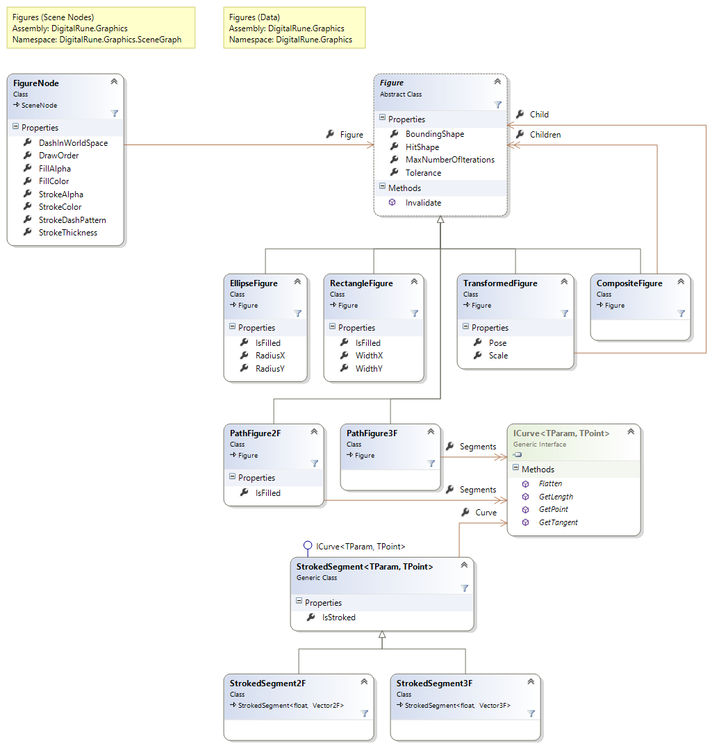
The class Figures is the base class for a range of types. EllipseFigure and RectangleFigure can be used to create simple 2D shapes. It is possible to transform and group figures using the TransformedFigure and the CompositeFigure.
PathFigure2F and PathFigure3F can be used to define complex 2D and 3D figures. Both classes are composed of line segments where each segment is described by an ICurveTParam, TPoint. DigitalRune Mathematics provides several curve classes in the namespace DigitalRune.Mathematics.Interpolation. These classes can be used to create straight lines, splines or complex paths. By default, all segments of a path figure get stroked. The StrokedSegmentTParam, TPoint decorator can be used to define whether a line segment that is stroked. A PathFigure2F can be filled, but PathFigure3F is a pure line drawing that cannot be filled.
When a renderer draws curved lines, it might convert them to a series of line segments. The properties MaxNumberOfIterations and Tolerance define how accurate such an approximation should be.
Each figure has a BoundingShape that can be used for frustum culling and a HitShape that can be used for accurate hit testing.
To add a figure to a scene a FigureNode must be added. The FigureNode references a Figure and allows to define the appearance of the shapes. The Stroke properties describe how the shape's outline is rendered. The stroke is rendered as an anti-aliased line and can use a dash pattern. Closed shapes can be filled with a solid color, defined by the Fill properties. (Some figures, like simple lines, do not have an interior and cannot be filled.)
Multiple FigureNodes can reference the same Figure. This can be used to define a common figure (e.g. an arrow symbol) once, and draw the figure several times in a scene with different appearances.
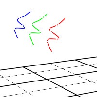
Figures can be used to render anti-aliased lines with dash pattern:
Figures can also be used to create various shapes:
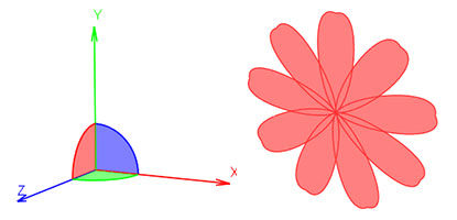
The following example code creates a 2D drawing that resembles a flower and adds it to a scene.
// Define single flower petal.
var petalPath = new Path2F
{
  new PathKey2F
  {
    Parameter = 0,
    Interpolation = SplineInterpolation.Bezier,
    Point = new Vector2F(0, 0),
    TangentIn = new Vector2F(0, 0),
    TangentOut = new Vector2F(-0.2f, 0.2f)
  },
  new PathKey2F
  {
    Parameter = 1,
    Interpolation = SplineInterpolation.Bezier,
    Point = new Vector2F(0, 1),
    TangentIn = new Vector2F(-0.3f, 1.1f),
    TangentOut = new Vector2F(0.3f, 1.1f)
  },
  new PathKey2F
  {
    Parameter = 2,
    Interpolation = SplineInterpolation.Bezier,
    Point = new Vector2F(0, 0),
    TangentIn = new Vector2F(0.2f, 0.2f),
    TangentOut = new Vector2F(0, 0)
  }
};

var petal = new PathFigure2F();
petal.Segments.Add(petalPath);

// Duplicate and rotate flower petal several times.
const int numberOfPetals = 9;
var flower = new CompositeFigure();
flower.Children.Add(petal);
for (int i = 1; i < numberOfPetals; i++)
{
  var transformedPetal = new TransformedFigure(petal)
  {
    Pose = new Pose(Matrix33F.CreateRotationZ(i * ConstantsF.TwoPi / numberOfPetals))
  };
  flower.Children.Add(transformedPetal);
}

// Add figure to the scene.
var flowerNode = new FigureNode(flower)
{
  Name = "Flower",
  StrokeThickness = 2,
  StrokeColor = new Vector3F(1, 0.2f, 0.2f),
  FillColor = new Vector3F(1, 0.5f, 0.5f),
  FillAlpha = 1,
  PoseLocal = new Pose(new Vector3F(3, 1, 0)),
  ScaleLocal = new Vector3F(0.5f)
};
scene.Children.Add(flowerNode);
The FigureRenderer is a SceneNodeRenderer that handles FigureNodes. The renderer can render filled shapes and stroked lines using anti-aliasing, different thickness and dash patterns.
Figures may be rendered on top of a scene (always visible) or as part of the current scene (to hide figures occluded by geometry). This is defined by setting the appropriate depth-stencil state. Alpha-blending can be used as well.
// Set desired depth-stencil and blend states.
graphicsDevice.DepthStencilState = DepthStencilState.DepthRead;
graphicsDevice.BlendState = BlendState.AlphaBlend;

// Render a list of figure nodes.
figureRenderer.Render(sceneNodes, context);
Figures are usually rendered with alpha-blending and without writing to the depth buffer. This means that the depth test can't be used for sorting figures, overlapping figures may be rendered in the wrong order. Most cases can be solved by choosing the right RenderOrder when calling the Render. However, there is not yet a general solution that works in all cases.